


Precision LVDT/RVDT Simulator, Isolated, Ethernet, USB-C
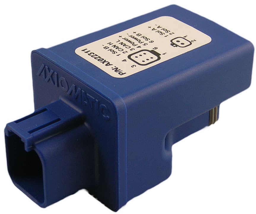
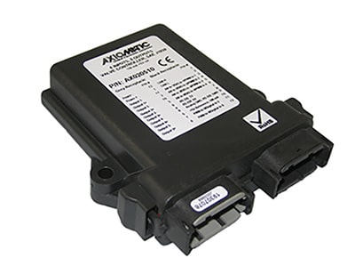
Item # AX130410 — Precision LVDT/RVDT Simulator, Isolated, Ethernet, USB-C


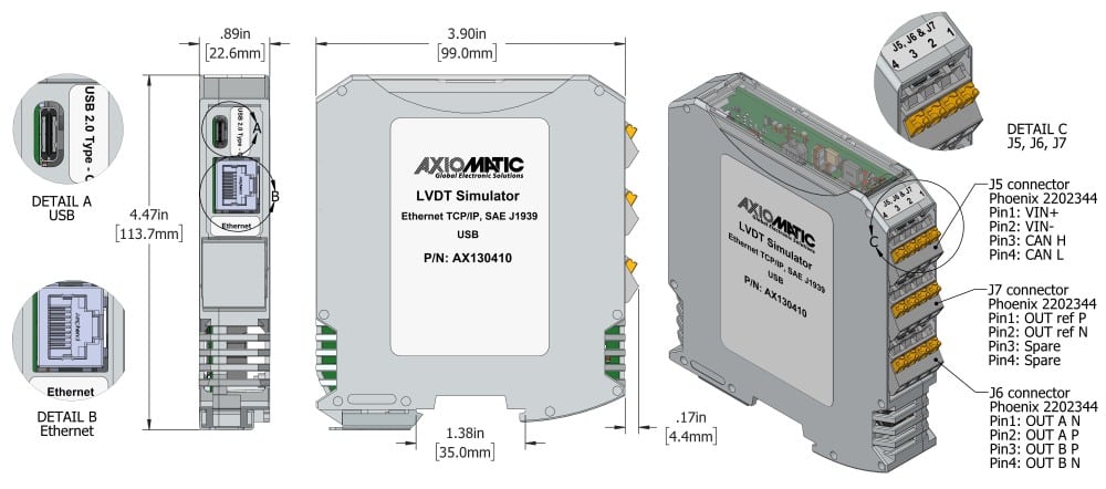
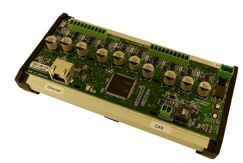
The AX130410 Precision LVDT/RVDT Simulator simulates LVDT/RVDT signals with high precision for use in various industrial applications. It is based on FPGA technology and uses 16-bit resolution for precision. AX130410 features one control input, one excitation input, and two LVDT/RVDT simulation outputs. On command, Output A increases from 0 to 9 VP-P (0-3.182 VRMS) and Output B decreases from 9 to 0 VP-P (3.182 VRMS). This voltage range is configurable. The two LVDT/RVDT simulation outputs are fully isolated. Phase delay between external excitation source and simulation outputs is programmable from 0 to 360°. An additional output at reference voltage of 3 VP-P (1.061 VRMS) is provided. The frequency of the outputs matches the selected excitation source (internal or external). The AX130410 controller features web, CAN, and USB interfaces via an RJ45 Ethernet TCP/IP port, an SAE J1939 CAN port, and a USB-C port. All settings can be configured, the firmware can be re-flashed, and the outputs can be controlled from the Ethernet port using a standard web browser. AX130410 can also interface with an SAE J1939 CAN network to provide command messages. The LVDT/RVDT Simulator operates at 12 or 24 VDC nominal (8 to 36 VDC) power. The unit enclosure features a DIN rail mount and an ingress protection rating of IP20.
Our products are designed to be customized by our customers and can be thought of as product foundations. Find the foundational product(s) that you need in our catalog, add them to your quote cart, then explain your requirements for your project on the quote cart submission form. If you cannot find the foundational product, please tell us your requirements.
Downloads
Datasheet

User Manual
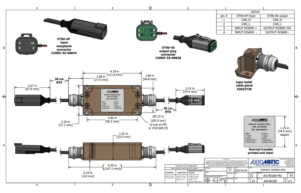
2D Drawing
3D Model


All Product Categories
Automation
Power Management
Connectivity Solutions
Machine Control
Accessories


- Flat Top Recessed Bumpers
- Rounded Top Recessed Bumpers
- Large Bumper Pads
- Grommet Bumper A


- Flat Top Recessed Bumpers
- Rounded Top Recessed Bumpers
- Large Bumper Pads
- Grommet Bumper A


- Flat Top Recessed Bumpers
- Rounded Top Recessed Bumpers
- Large Bumper Pads
- Grommet Bumper A
- Flat Top Recessed Bumpers
- Rounded Top Recessed Bumpers
- Large Bumper Pads
- Grommet Bumper A
Note: Axiomatic Electronic Assistant (EA) programs are located under “EA & Other Configuration Tools” under the “Support” tab. Please contact Axiomatic for the password.
View All
- Flat Top Recessed Bumpers
- Rounded Top Recessed Bumpers
- Large Bumper Pads
- Grommet Bumper A